
Abstract: The sealing diaphragm is an important component in welded sealed weighing/measuring load cells. When designing, the sealing membrane should not only ensure the sealing performance of the load cell, but also minimize the impact of the membrane itself on the load cell performance as much as possible; Therefore, optimizing design is a necessary step. This article optimizes the design of cup shaped sealing membranes using Pro/Mechanica software. This method also has certain reference value for parameter optimization of other types of membranes.
Keywords: diaphragm; Pro/Mechanica; Load load cell; optimal design
Introduction:
The usage environment of resistance strain type load (weighing) load cells is sometimes very harsh. In such environments, if the load cell is not effectively and reliably sealed, it will fail in the short term. So, in order to ensure that load cells can work stably and normally in this environment for a long time, many companies’ products generally adopt a fully sealed method of metal welded diaphragms. This fully sealed method is a very effective solution, ensuring the working reliability and long-term stability of the load cell; However, if the structure design of the sealing diaphragm is not reasonable, it will directly affect the accuracy of the load cell, so it is necessary to optimize the design of the diaphragm.
Depending on the structure of the load cell, there are several different types of sealing membranes, such as flat membranes, corrugated flat membranes, cup shaped membranes, metal corrugated pipes, and so on. However, for any type of structure, if traditional design methods are used, the calculation is cumbersome and the accuracy is not high. This article optimizes the design of cup shaped sealing membranes using Pro/Mechanica software. Pro/Mechanica is a CAE analysis software integrated under the Pro/Engineer software of PTC company, which has the characteristics of simple operation and seamless integration with CAD.
1:Establishing an analytical model
The structural dimensions of the cup type sealing diaphragm are shown in Figure 1, with the main structural dimensions being D, D1, R1, R2, and H. The thickness of the diaphragm is a fixed value of 0 1mm. Dimension D is limited by the elastic structure design of the load cell and is also considered a fixed value. So there are four design variables for the diaphragm: D1, R1, R2, H (initial values are 20mm, 2mm, 1mm, 10mm, respectively).

Figure 1 Dimensions of Cup Diaphragm
In order to analyze the impact of cup shaped diaphragm structure on load cell performance, we imported the assembly components of the diaphragm and elastomer into Pro/Mechanica for analysis. Verify and optimize the diaphragm structure by analyzing the impact of changes in the cup diaphragm structure on the strain distribution in the sensitive area of the load cell. In the analysis model, the rated load of the load cell is 50kg, and the application point is on the installation surface of the elastomer, while the constraint is applied on the installation surface below the elastomer, as shown in Figure 2.
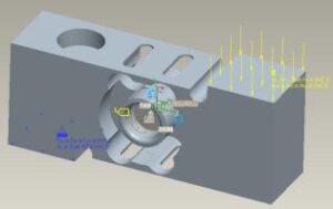
Figure 2 Diaphragm and Elastomer Assembly Model
The elastomer material is 0Cr17Ni4Cu4Nb, the elastic modulus is set as 200GPa, and the Poisson’s ratio is 0.28; The diaphragm material is 304L, the elastic modulus and Poisson’s ratio are the same as those of the elastomer, and the yield strength of the diaphragm material is 210MPa.
The elastic body adopts the default tetrahedral element, and the diaphragm uses the default shell element for grid division. The diaphragm and elastomer are connected using the Bond method in Pro/Mechanica, ignoring the influence of welding process on the assembly parts.
In addition, because the load cell is an inner hole patch, the center axis of the inner hole is used as the benchmark to establish a Cylindrical coordinate system, which is convenient for analyzing the circumferential stress distribution results of the patch area.
2:Static analysis of the model
As a preliminary stage of optimization design, it is necessary to conduct static analysis of the model, including stress analysis before the elastic body is welded to the diaphragm and stress analysis after the elastic body is welded to the diaphragm. Establish corresponding static analysis and calculation through the File menu under New Static. The results are as follows: When the elastic body is not welded to the film, the circumferential stress distribution in the patch area is shown in Figure 3; After the elastic body is welded onto the membrane, the circumferential stress in the patch area
The force distribution is shown in Figure 4.

Figure 3 Circumferential stress distribution in the patch area of an elastic body without welding the diaphragm
By comparing the maximum circumferential stress value (max_strain_TT) in the patch area before and after welding (1258 microstrain before welding, 1188 microstrain after welding), it can be found that before optimizing the diaphragm size, the rated output of the load cell after welding the diaphragm is expected to decrease by 5.56% compared to before welding the diaphragm.
3:Sensitivity analysis of membrane parameters
Sensitivity analysis can determine the magnitude of the impact of each parameter in the model on the output results. In the optimization process of the model in the future, focus on those parameters that have a significant impact on the output results, while ignoring those parameters that have a smaller impact on the output results. This can reduce the workload of later optimization design and improve efficiency. Pro/Mechanica provides two functions in sensitivity analysis: local sensitivity analysis and global sensitivity analysis. Local sensitivity calculates the degree to which small changes in various parameters in the model (Pro/Mechanica defaults to 1% variation) affect the output results of the model; The global sensitivity requires first determining the range of changes in each parameter in the model, and then calculating the impact of changes in each parameter throughout the entire range on the output results. According to Pro/Mechanica’s definition of two types of sensitivity analysis, local sensitivity can be used as a qualitative analysis of the problem, while global sensitivity is more suitable for quantitative analysis of the problem. Therefore, we use local sensitivity analysis to confirm the importance of each parameter, and choose the maximum circumferential stress in the patch area (max_strain_TT) and the maximum equivalent stress of the membrane (max_stress_vm) as the most observed results. The calculation results of each parameter are summarized as shown in Figure 5 and Figure 6.
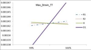
Figure 5: The influence of various parameters on the maximum circumferential stress output in the patch area
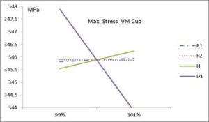
Figure 9: The influence of various parameters on the maximum equivalent stress (Von Mises) output of the diaphragm.
According to Figures 5 and 6, it can be seen that parameter D1 has the most significant impact on the load cell output, followed by parameter H, and the remaining R1 and R2 are the least significant. However, it should be considered that R1 and R2 may not have a significant impact on the output due to their small initial values and relatively small absolute changes during local sensitivity analysis. Ultimately, four parameters were chosen for optimization design.
4:Optimization analysis and validation of membranes
The so-called optimization design is a design method that selects the best solution from multiple options. It is based on the optimization theory in mathematics and uses calculation as a means to establish an objective function based on the performance goals pursued by the design. Under the given constraints, it seeks the most
Excellent design solution. Generally speaking, optimization design includes three elements: optimization objectives, optimization constraints, and optimization parameters. In the optimization design of the diaphragm, these three elements are:
Optimization objective – the maximum average strain value in the circumferential direction of the patch area, with a specific setting goal of: max_ Strain_ The maximum value of TT;
Optimization constraint – the maximum equivalent stress of the diaphragm is less than the allowable stress of the diaphragm material (considering the actual situation of this example, set the Factor of safety S=1), and the specific setting is max_ Stress_ VM_ Cup<210MPa;
Optimization parameters – sensitivity analysis results: all four variables need to be considered. Furthermore, considering factors such as manufacturing processes,
The specific range of each optimization parameter is set as follows: (D1)/2=6-10.4mm, R1=1-2.4mm, R2=1-3mm, H=6-12mm.
After completing the above parameter settings, start the calculation and finally obtain the optimized parameter size as shown in Figure 7:
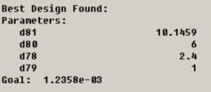
Figure L Optimized Parameter Size
According to the optimized diaphragm size update model, stress analysis was conducted again after welding the elastic body diaphragm, and the results are shown in Figure 8:
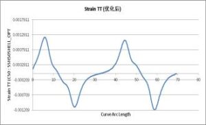
Figure 8: Circumferential stress distribution in the patch area after membrane optimization
After welding, max_ Strain_ The TT value is 1204 microstrain, an increase of 1.35% compared to before optimization, indicating that the optimized diaphragm is expected to reduce the rated output value of the load cell by 4.29% after welding.
According to the optimized diaphragm, the test results of the rated output values of the three prototypes before and after welding are shown in Table 1:
Table 1: Changes in rated output values of the tested prototype before and after welding
| Prototype No. | Before Welding Span (mv/V) | After Welding Span(mv/V) | Impact Quantity (%) |
| 1 | 2.025723 | 1.928325 | 4.82 |
| 2 | 2.055369 | 1.961534 | 4.56 |
| 3 | 2.073309 | 1.970722 | 4.95 |
It can be seen that the calculation results of CAE are relatively close to the actual prototype test results, and the settlement results of CAE are generally small.
5:Conclusion
Optimizing the design of cup shaped diaphragms through Pro/Engineer’s CAD/CAE integrated platform is a fast and effective optimization method that avoids a lot of manual calculation and analysis work. This method also has certain reference and guidance significance for parameter optimization of other types of membranes.